
POWER SYSTEMS |
POWER SYSTEMS |
 |
|||||
|
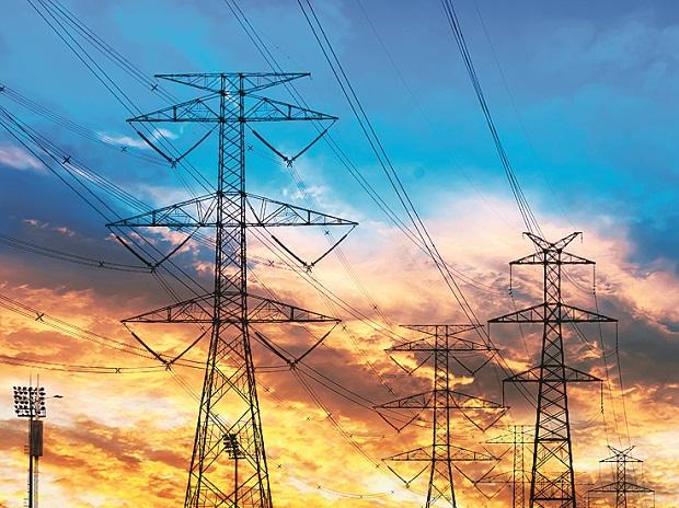
Electrical power transmission involves the bulk movement of electrical energy from a generating site, such as a power station or power plant, to an electrical substation where voltage is transformed and distributed to consumers or other substations. The interconnected lines that enable the movement of electrical energy are known as a “transmission network,” and these form an electrical power transmission system—or, as it is more commonly known, the power grid.
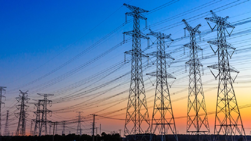
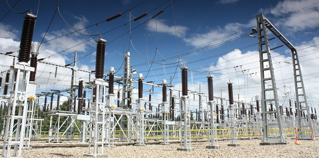
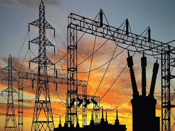
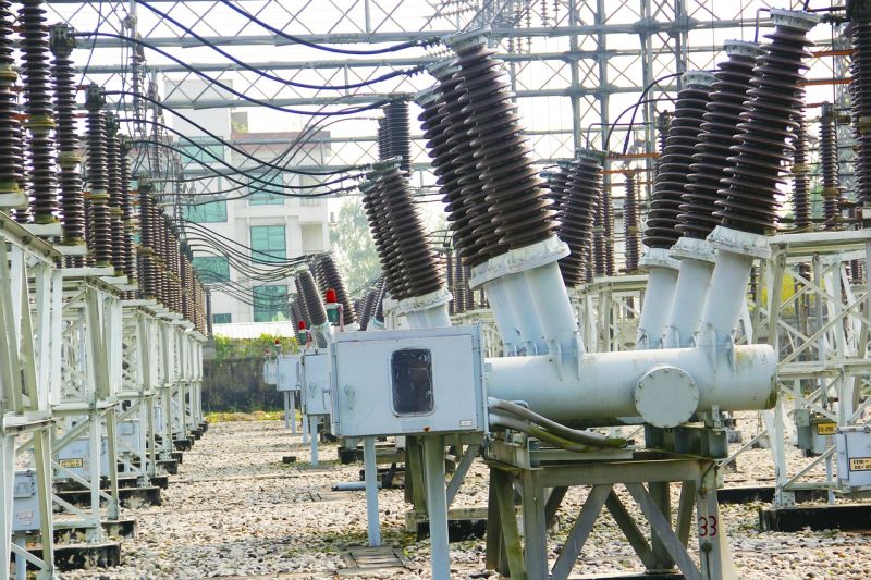
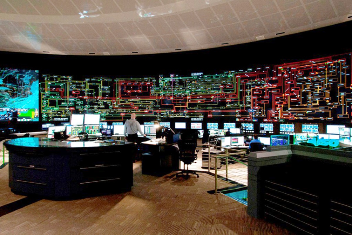
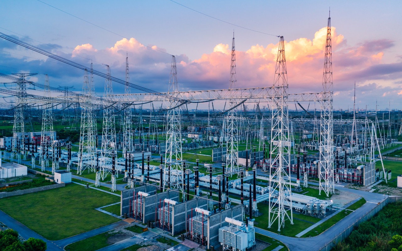
When it is generated at a power station, electrical energy will typically be anywhere between 11kV and 33kV. Before it is sent to distribution centers via transmission lines, it is stepped up using a transformer to a voltage level that can be anywhere between 100kV and 700kV or more, depending on the distance that it needs to be transmitted; the longer the distance, the higher the voltage level. The reason electrical power is stepped up to these voltage levels is to make it more efficient by reducing the I2R losses that take place when power is transmitted. When voltage is stepped up, the current reduces relative to the voltage so that power remains constant, thus reducing these I2R losses. This stage is known as primary transmission—the transfer of a large quantity of electrical power from the initial generating station to the substation via overhead electrical lines. In some countries, underground cables are also used in cases where transmission takes place over a shorter distance. When electrical power reaches a receiving station, the voltage is stepped back down to a voltage typically between 33kV and 66kV. It is then sent to transmission lines emerging from this receiving station to electrical substations closer to “load centers” such as cities, villages, and urban areas. This process is known as secondary transmission. The main components of high-voltage electric transmission lines and associated facilities include: * Transmission towers are the most visible component of the power transmission system. Their function is to keep the high-voltage conductors (power lines) separated from their surroundings and from each other. A variety of tower designs exist that generally employ an open lattice work or a monopole, but generally they are very tall * Conductors are the power lines that carry the electricity to and through the grid to consumers. Generally, several conductors are strung on a tower for each electrical circuit. Conductors are constructed primarily of twisted metal strands, but newer conductors may incorporate ceramic fibers in a matrix of aluminum for added strength with lighter weight. * Substations transform voltage from high to low, or the reverse, or perform any of several other important functions.A transmission substation connects two or more transmission lines. The simplest case is where all transmission lines have the same voltage. In such cases, substation contains high-voltage switches that allow lines to be connected or isolated for fault clearance or maintenance. A transmission station may have transformers to convert between two transmission voltages, voltage control/power factor correction devices such as capacitors, reactors or static VAR compensators and equipment such as phase shifting transformers to control power flow between two adjacent power systems. Power system operators often describe two elements of electric system reliability: adequacy and security. Adequacy is the ability of the electric system to supply the electrical demand and energy requirements of customers at all times, taking into account scheduled and unscheduled outages of power lines and power plants. Security is the ability of the electric system to withstand sudden disturbances such as electric short circuits or unanticipated loss of system facilities such as a power plant or a power line. The transmission system gives power users the ability to draw from a diverse set of power plants in different locations and with different operating characteristics. If the transmission system is robust, with a certain amount of redundancy built in, it can withstand the failure of its most critical lines or other components. Analysts often refer to this as single contingency analysis, or N-1 analysis. This robustness and diversity create a network of power plants and lines that is far more reliable than one that relies on the output from a single plant or a single line. In the end, an interconnected power system needs fewer power plants to meet customers’ electricity demands because all the power plants can use the transmission system to share the responsibility of meeting customers demand. SCADA/EMS (Supervisory Control and Data Acquisition and Energy Management System ) challenge is to ensure these changing power system operating conditions stay within safe limits in the present and during potential future contingencies as well. SCADA’s data acquisition is accomplished through an integrated combination of software and hardware. The applications, the e-terracontrol front end, related communications front-end protocol translation code, ICCP communication gateways, and RTUs work in parallel to support continuous data exchange. Real time applications use SCADA telemetered data to maintain a consistent estimate of the current network state, to evaluate the impact of hypothetical outages and switching actions on the network security, to optimize of real power outputs in presence of network limitations, to evaluate the breaker capability to withstand fault currents. Study applications analyze user-specified operating conditions. The generation application encompasses the entire range of real-time generation scheduling, monitoring and control functions. System Load Forecast application produces a weather dependent forecast of system load. The role of the Dispatcher Training Simulator subsystem is to provide a realistic environment for network behavior simulation, operator training, and software testing. The flexible, scalable and extensible phase-based Wide Area Management System (WAMS) can be integrated with EMS. The massive amount synchrophasor measurement needs to be converted into useful, operator-actionable information. The range of advanced analytics currently available includes: angular separation, oscillatory stability, disturbance location identification, islanding and resynchronization.
| |
        |

